H = feedback (G,K) H = s 2 s^2 25 s 7 Continuoustime transfer function To compute H from the formula, type H2 = G/ (1G*K) H2 = s^3 25 s^2 4 s 6A unityfeedback MIMO control system is formed of a proportional controller and a plant whose transfer function matrices are Analyze the stability of this system Solution The followingControl Systems Transfer Function of a Closed Loop and Open Loop SystemsTopics discussed1 The transfer function of an open loop system2 Closed loop syst
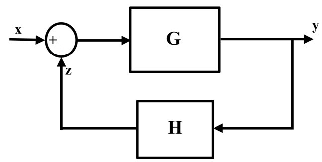
Negative Feedback System
Feedback transfer function formula
Feedback transfer function formula-Define the feedout and feedin vectors based on the inputs and outputs to be connected in a feedback loop feedin = 2 4;Transfer Function = Output of system / Input of System G(s) = C(s) / R(s) This formula uses 3 Variables Variables Used Transfer Function Transfer function of an electronic or control
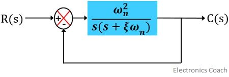


Time Response Of Second Order System Electronics Coach
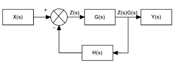
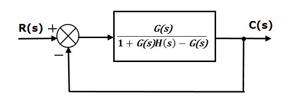
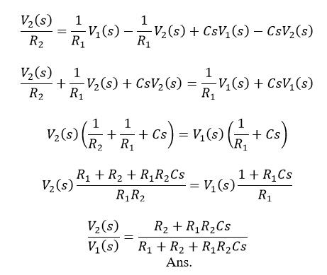
As before, we may derive a transfer function by expressing \(V_{out} / V_{in}\) as a ratio of the resistor's impedance to the total series resistorcapacitor impedance (treating this as a voltageThe summing node and the G(s) and H(s) blocks can all be combined into one block, which would have the following transfer function Y ( s ) X ( s ) = G ( s ) 1 G ( s ) H ( s ) {\displaystyle {\dfrac( ) ( ) = R s C s 1 ( ) ( ) ( ) G s G s R s C
Without feedback y(t) = g(x(t)), where g is called gain and is a functionanything from multiplication by a constant to a differential equation With negative feedback an error = xf' isK = rss (3,2,3);Lecture Unity Negative Feedback and Unity Positive Feedback Control System with Transfer Function Linear Control SystemsName Dr Krishna SarkerLectur
In engineering, a transfer function (also known as system function or network function) of a system, subsystem, or component is a mathematical function that theoretically models theUnity Feedback System C(s)E(s) G(s) R(s) Desired input System output Error, E(s)=R(s)C(s) "Open Loop" Transfer Function Unity Feedback System?Feedout = 1 3 4;
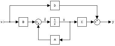


Control Systems Feedback Loops Wikibooks Open Books For An Open World
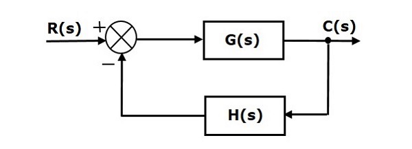


Control Systems Steady State Errors
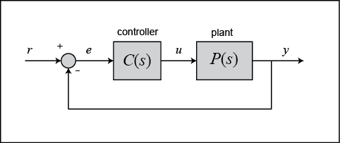
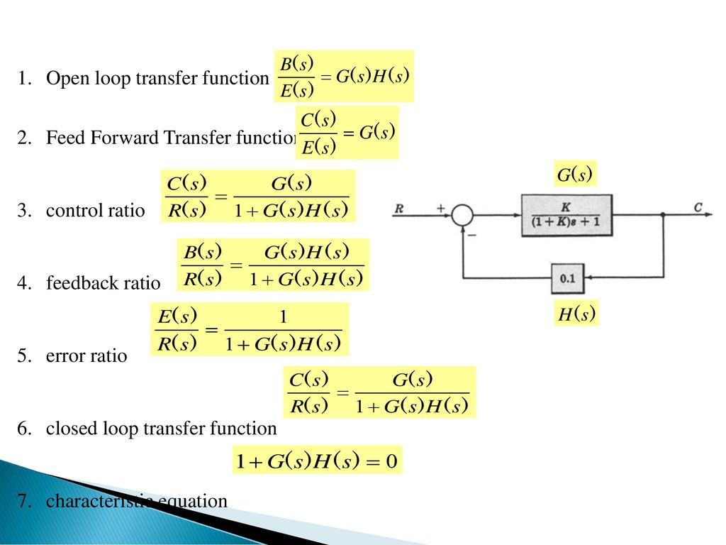
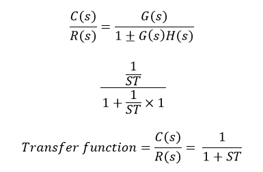
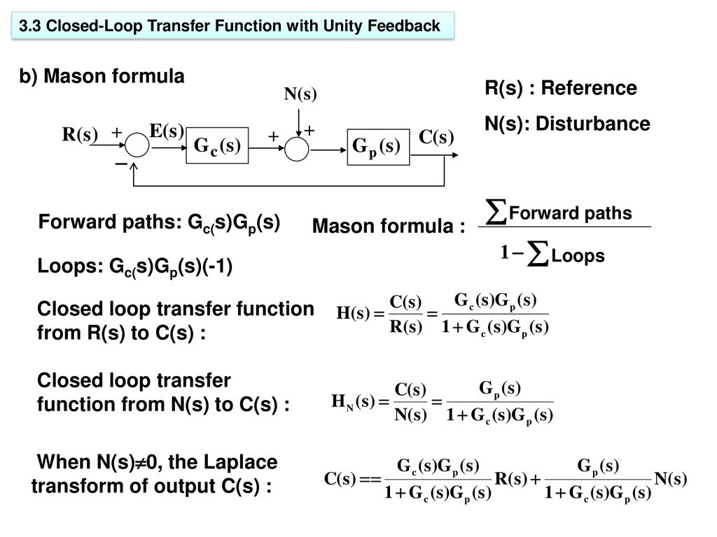
Determine the feedforward transfer function G(s) and the feedback transfer function H(s) of a negativefeedback system that implements the overall transfer function Y ( s ) X ( s ) = K K s$T=\frac{G}{1GH}$ (Equation 1) Where, T is the transfer function or overall gain of positive feedback control system G is the open loop gain, which is function of frequency H is the gain of feedback path, which is function of frequency Negative Feedback Negative feedback reducesFig 1 closed loop system Referring to Figure 1, the ratio of the feedback signal B (s) to the actuating error signal E (s) is called the openloop transfer function That is, The ratio of the


Negative Feedback System


Transformation Single Diff Eq Transfer Function
G = rss (3,4,5);Feedback Equation The feedback equation is(219)uf=Kfxtwhere Kf is the feedback gain From Commercial Aircraft Hydraulic Systems, 16 Related terms Transfer Function;The transfer function is represented in the z domain (52) where z−1 = exp (− sTs) is called the unit delay operator, since multiplication by z−1 is equivalent to delaying the sequence by one


Closed Loop Control System Block Diagram Types Its Applications


Q Tbn And9gcsv Sg3xqhyurxiuf7lpvncgredlkhgkrte9mwesb25y4ggz0i5fpyq Usqp Cau
Transfer function of a Negative Feedback System In order to analyze and understand the operation of a feedback system, we need to obtain its YS) transfer function H (s) This functionThere is a direct relationship between transfer functions and differential equations This is shown for the secondorder differential equation in Figure The homogeneous equation (the left


Control Tutorials For Matlab And Simulink Introduction Pid Controller Design


Control Systems Steady State Errors


Determining Stability Using The Nyquist Plot


Control Tutorials For Matlab And Simulink Extras Steady State Error


2 A Feedback And B Parallel Decomposition Of A Generic M N 2 Download Scientific Diagram


Compute Open Loop Response Matlab Simulink
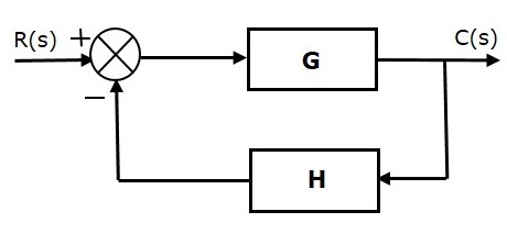


Control Systems Feedback


Ebook Dynamic System Modeling And Control


Assessing Gain And Phase Margins Matlab Simulink


Multivariable Control Dynamics And Control With Jupyter Notebooks 0 0 1 Documentation


Negative Unity Feedback System Transfer Function Of The Plant Is An Download High Quality Scientific Diagram
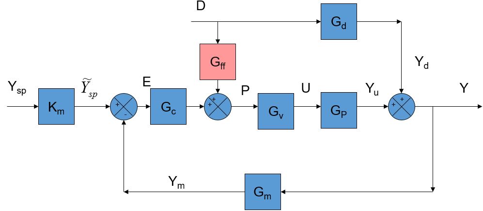


Feedforward Control Dynamics And Control


Negative Feedback System


Closed Loop Control System


Control How Can I Calculate Gain Margin In This Transfer Function And The Constant K Electrical Engineering Stack Exchange
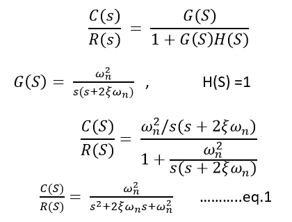


Control System Time Response Of Second Order System Javatpoint


Intro To Control 10 2 Closed Loop Transfer Function Youtube


M5a Summary Summary 5 Feedback Control System And Pid Control 1 Feedback Control Closed Loop Studocu


Transfer Function Of Control System Electrical4u


Solved Q 3 The Closed Loop Transfer Function Of A System Is Chegg Com


2
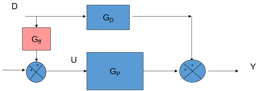


Feedforward Control Dynamics And Control
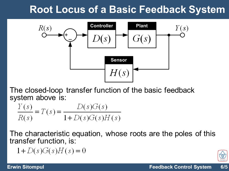


Feedback Control System The Root Locus Design Method Dr Ing Erwin Sitompul Chapter 5 Ppt Download


Block Diagram Fundamentals
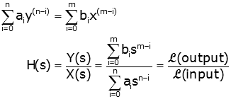


Transfer Function Representations Of Linear Physical Systems
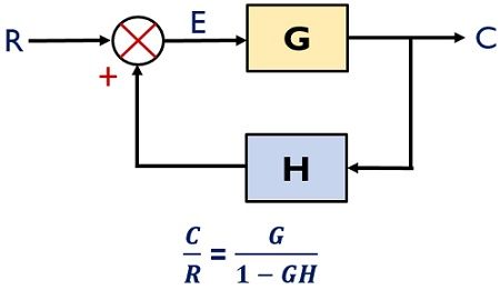


What Is Feedback System Block Diagram And Types Of Feedback Electronics Coach


4 1 Stability Of The Closed Loop System Engineering Libretexts


Feedback Systems And Feedback Control Systems


Feedback Equation An Overview Sciencedirect Topics
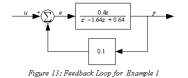


Wescott Design Services Using Block Diagrams


Cascade Connection An Overview Sciencedirect Topics
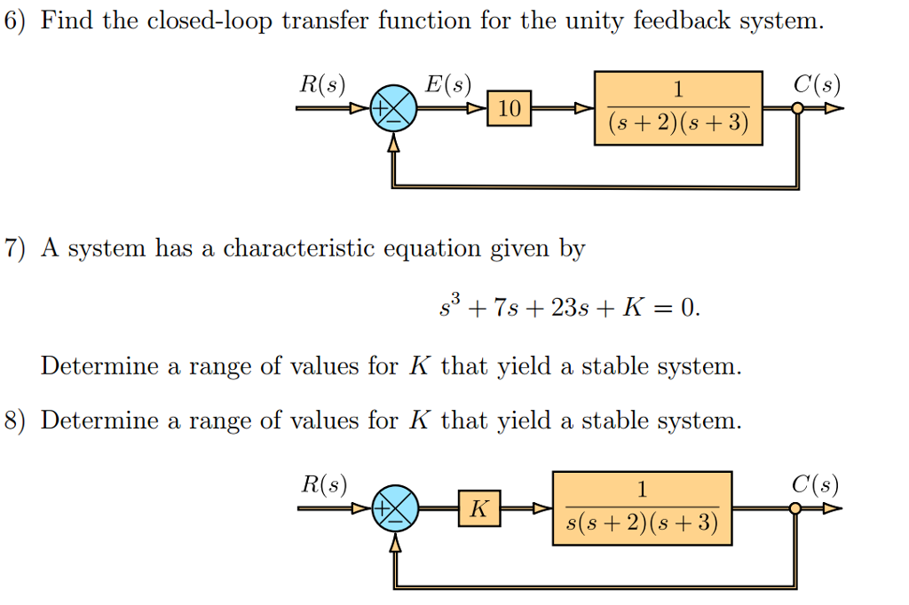


Solved Find The Closed Loop Transfer Function For The Unity Chegg Com
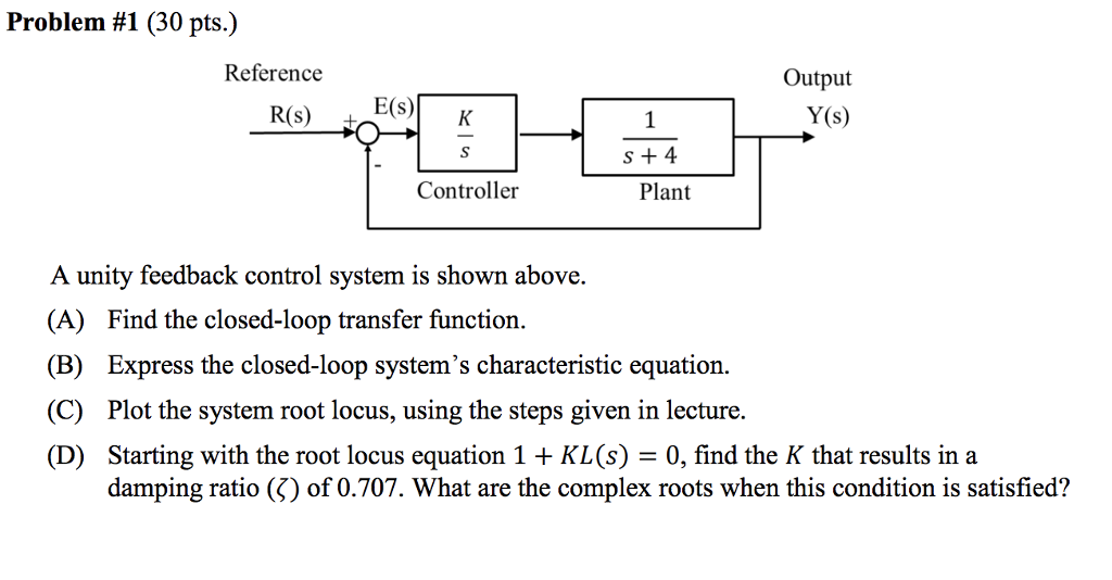


Solved Problem 1 30 Pts Reference Output Y S R S E S Chegg Com
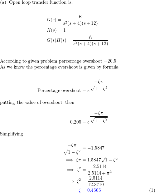


A Unity Feedback Control System Has The Following Forward Tr Quizlet
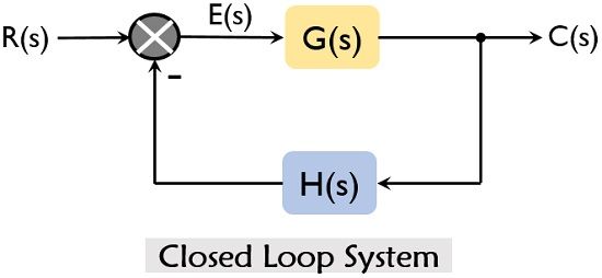


What Is Closed Loop Control System Definition Operation And Transfer Function Of Closed Loop Control System Electronics Coach


Ee 212l Mft Bpf Fs


Gate Ese Closed Loop Tf And Characteristic Equation Offered By Unacademy


Closed Loop System And Closed Loop Control Systems
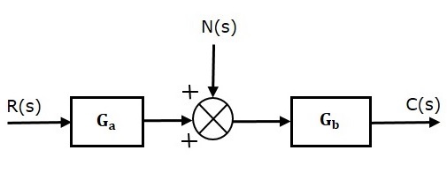


Control Systems Feedback
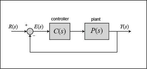


Control Tutorials For Matlab And Simulink Extras Steady State Error


Control System Transfer Function Javatpoint
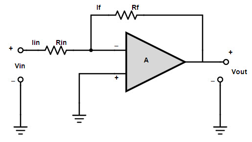


Negative Feedback System
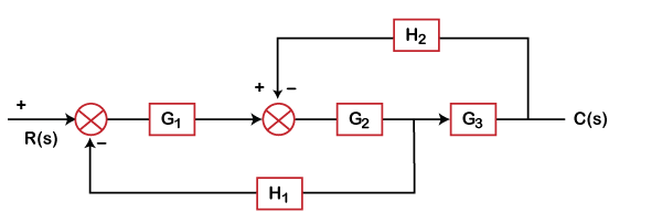


Control System Mcq Multiple Choice Questions Javatpoint


Negative Feedback And Negative Feedback Systems


Problem 1 On Block Diagram Reduction Youtube
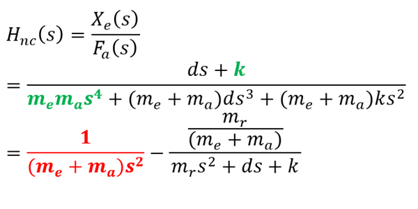


4th Order Systems Interpretation Jpe


Loop Transfer Function An Overview Sciencedirect Topics


Loop Transfer Function An Overview Sciencedirect Topics
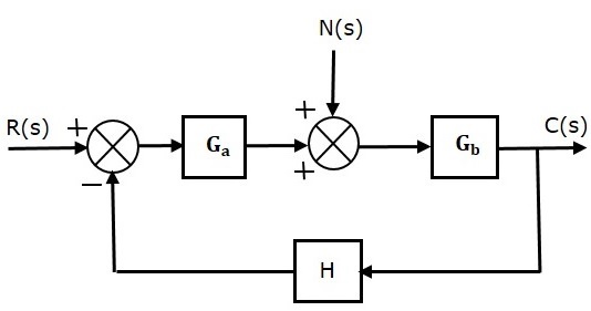


Control Systems Feedback


Dc Dc Converter Control Feedback Control Loop Youtube


Block Diagrams 8 Tutorial Sheet On Closed Loop Transfer Functions And Use Of Matlab Youtube


Finding Gain And Time Constant From A Transfer Function Model Youtube


Transfer Function Of Control System Electrical4u
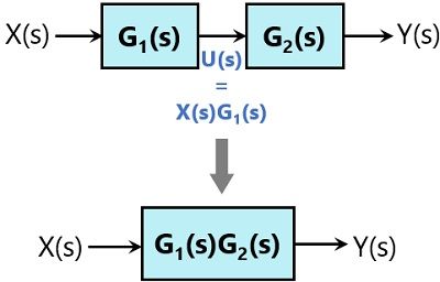


Block Diagram Reduction Rules With Example Electronics Coach


Transformation Single Diff Eq Transfer Function


Transfer Function Of A Closed Loop System Youtube


Time Response Of Second Order Control System Worked Example Electrical4u


Transfer Functions An Overview Sciencedirect Topics


Steady State Error An Overview Sciencedirect Topics
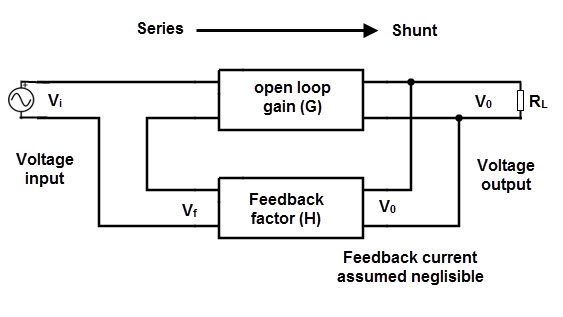


Negative Feedback System
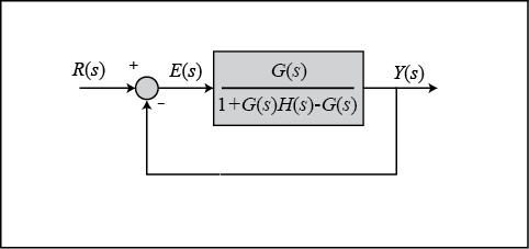


Control Tutorials For Matlab And Simulink Extras Steady State Error


Root Locus Plot Of Dynamic System Matlab Rlocus
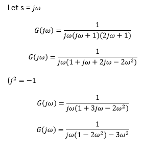


Control System Mcq Multiple Choice Questions Javatpoint
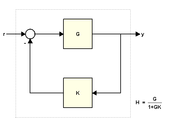


Using Feedback To Close Feedback Loops Matlab Simulink Example


Transformation Transfer Function State Space
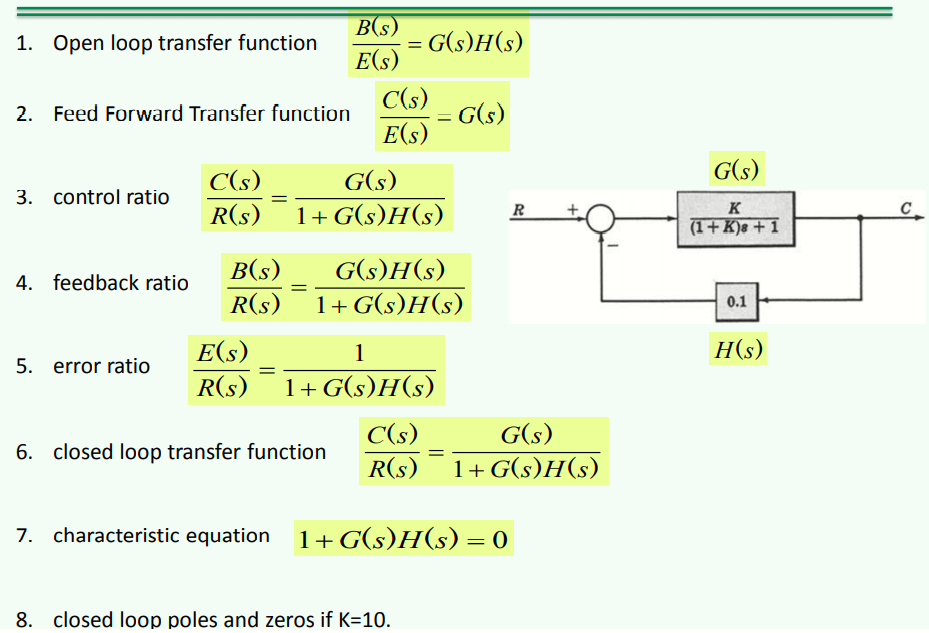


Solved My Teacher Asked Me To Prove These Equations Not Chegg Com


Loop Gain Wikipedia
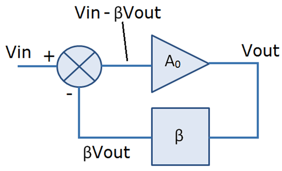


Loop Gain And Its Effect On Analog Control Systems Analog Devices
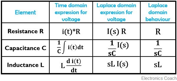


What Is Transfer Function Of Control System Procedure To Determine Transfer Function Advantages And Disadvantages Of Transfer Function Electronics Coach


Q Tbn And9gcrpk39j4dqimbhuddsdftupivnmy8dzp4iyczbfulfwczv6rjmosprf Usqp Cau


Q Tbn And9gcqrmj2xzcisjfwqqkpkdrlmv5v2ymy7ydwjflciozfj4eucjus4koq0 Usqp Cau


Standard Hw Problem 2 Which Is The Real Open Loop Transfer Function Youtube
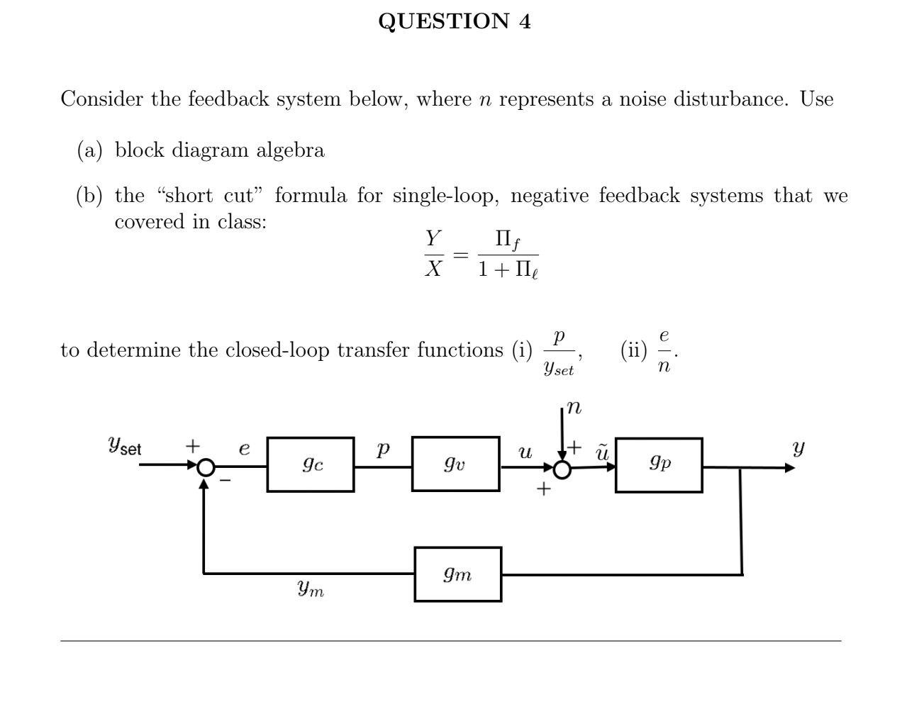


Solved Question 4 Consider The Feedback System Below Where Chegg Com


Closed Loop Transfer Function Wikipedia
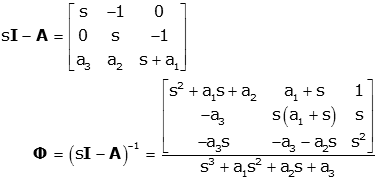


Transformation Transfer Function State Space


Time Response Of Second Order System Electronics Coach


Time Response Analysis Of Control System Presentation Powerpoint Slides


Control Systems Steady State Errors


2


Chapter 1 Introduction To Control Systems Ppt Download


Closed Loop System And Closed Loop Control Systems


Feedback Systems And Feedback Control Systems


Control System Transfer Function Javatpoint


Root Locus Examples


Control System Time Response Of First Order System Javatpoint


Solved B The System Below Features The Open Loop Transfer Chegg Com


3 Closed Loop Transfer Functions Ppt Download


First Order Control System What Is It Rise Settling Time Formula Electrical4u
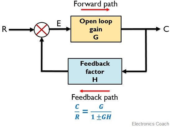


What Is Feedback System Block Diagram And Types Of Feedback Electronics Coach


2


First Order Control System What Is It Rise Settling Time Formula Electrical4u


2
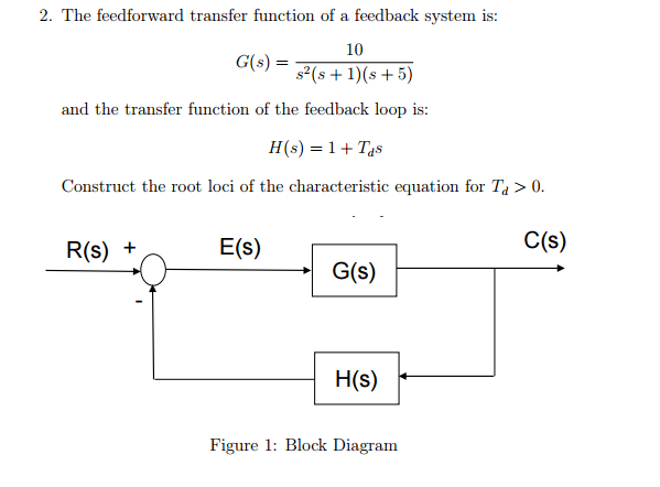


Solved Transfer Function Of A Feedback System Is 10 G S Chegg Com
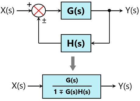


Block Diagram Reduction Rules With Example Electronics Coach


2


Loop Transfer Function An Overview Sciencedirect Topics


Closed Loop System And Closed Loop Control Systems
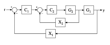


Open Loop Transfer Function Of Control System Represented By Genss Model Matlab Getlooptransfer


0 件のコメント:
コメントを投稿